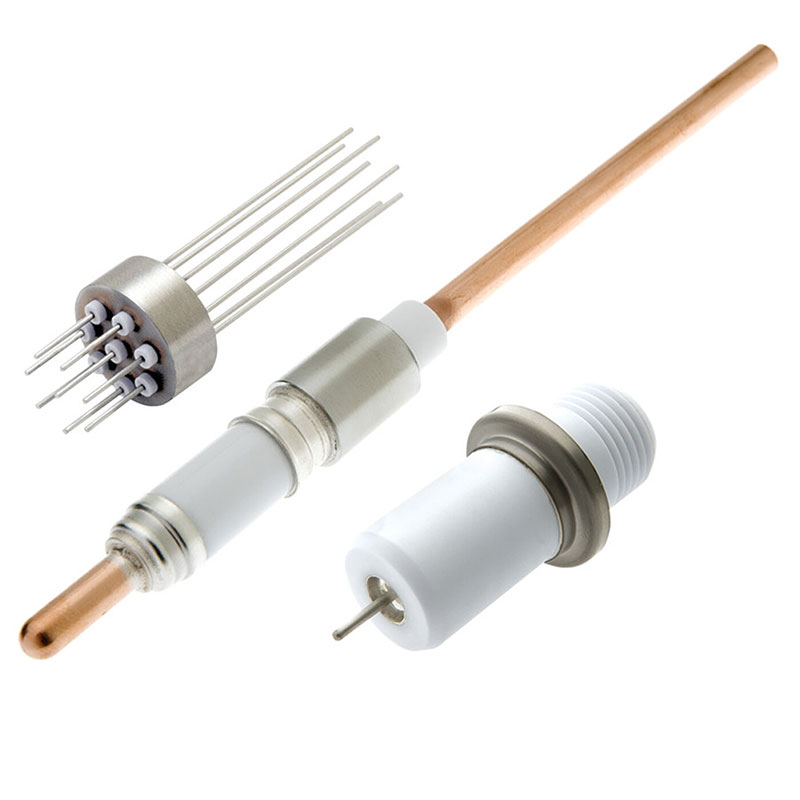
Precision in hard machining goes beyond standard CNC — alumina’s brittleness, sintering shrinkage, and surface integrity dictate every design choice before production starts
Engineers specifying alumina ceramic machined parts face a different challenge than metal or plastic components. High-purity alumina (Al₂O₃ ≥ 95%) offers exceptional hardness, compressive strength, and dielectric stability, but these same properties make post-sintering machining difficult and pre-sintering green-state processing unpredictable. This article explains how to select the right alumina grade, manage tolerances across firing and grinding stages, and validate critical features such as holes, edges, and sealing surfaces. You will also learn the primary failure modes — edge chipping, micro-cracking, and metallization adhesion loss — so that procurement and design teams can move beyond generic ceramic datasheets toward reliable, application-specific parts.
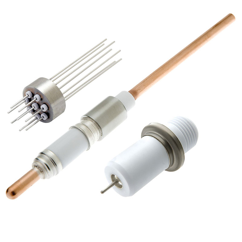
Alumina ceramic components are not simply high-temperature replacements for metals. They fundamentally change how a system manages wear, corrosion, and electrical isolation. In applications ranging from vacuum feedthroughs to medical fluidics and automotive sensors, the machined part’s final performance depends equally on raw powder processing and the sequence of diamond grinding, lapping, and polishing.
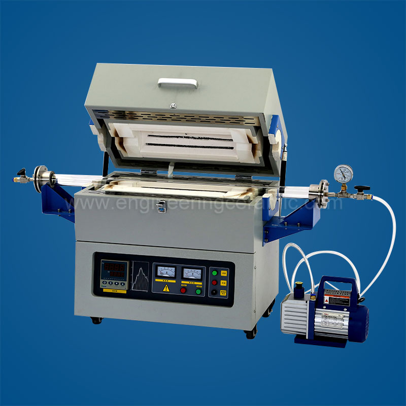
The relationship between as-fired dimensions and finished tolerances is critical. Typical sintering shrinkage for 96% to 99.8% alumina ranges from 15% to 20% linearly, with significant batch-to-batch variation. Machining after sintering — using diamond tooling — can achieve ±0.005 mm on bores and ±0.01 mm on flatness, but each stock removal pass risks introducing subsurface damage. Green-state machining (before firing) allows faster material removal and lower tool wear, but shrinkage anisotropy can distort holes and slots unpredictably. Experienced suppliers model both routes and select based on feature aspect ratio and quantity.
In semiconductor capital equipment, alumina end effectors and chamber liners must survive plasma erosion and extreme thermal cycling while maintaining sub-micron particle generation limits. Precision-machined grooves and vacuum ports cannot trap process gases. In medical implantable devices, alumina femoral heads demand Ra <0.01 µm surface finish and edge break control to avoid catastrophic fracture under cyclic load. For automotive ignition systems, insulator tips require consistent creepage distances and flashover resistance — any grinding burn or residual stress lowers dielectric strength by 30% or more.
Unlike ductile materials, alumina parts are defined by a combination of as-specified dimensions, surface integrity metrics, and statistical proof testing.
Alumina grades are distinguished by purity and average grain size. 95% to 96% alumina offers a balance of cost, strength (≈300–350 MPa flexural strength), and electrical resistivity (>10¹⁴ Ω·cm). 99.6% to 99.8% alumina increases flexural strength to 400–450 MPa and improves wear resistance but requires more expensive diamond finishing. Grain size directly affects edge toughness: fine-grain (1–3 µm) materials polish to smoother surfaces and resist micro-chipping, while coarse-grain (>5 µm) alumina is easier to green-machine but fractures more readily under point loading.
Critical specifications include:
| Process | Stock Removal | Surface Damage Risk | Typical Application |
|---|---|---|---|
| Green-state milling | High | Low (pre-firing) | Holes, slots, thin walls |
| Sintered-state diamond grinding | Medium | Medium | OD/ID, flat surfaces |
| Lapping | Very low | Minimal | Sealing faces, gauge surfaces |
| Ultrasonic machining | Low | Low | Complex 3D contours, fragile geometries |
Alumina parts rarely operate alone. They are often brazed, clamped, or shrink-fitted into metal housings. Differential thermal expansion (alumina ≈6–8 ppm/°C vs. stainless steel ≈17 ppm/°C) creates assembly stresses that must be managed by interference fit design. A typical rule: for a 10 mm diameter alumina pin in a steel housing, interference should not exceed 0.01–0.02 mm at room temperature to avoid fracture during insertion.
Metallization of alumina — typically molybdenum-manganese or active brazing alloys — requires the machined surface to have a specific roughness profile (approximately 0.4–0.8 µm Ra) for adhesion. Too smooth, and the metallization peels; too rough, and micro-cracks form under thermal cycling.
Qualified suppliers must provide:
Custom alumina machined parts typically require MOQs of 200–1,000 pieces for economic diamond tooling amortization. Lead times: green-state machining 2–3 weeks plus sintering cycle (3–5 days) plus finish grinding (1–2 weeks). Rush orders with existing tooling can be 10–15 days. Private labeling is not typical, but suppliers offer custom packaging (cleanroom-ready trays, lot-controlled bags) and certificate of conformance with each shipment.
| Market Tier | Price per piece (typical small part) | Purity & Machining | Key Characteristics |
|---|---|---|---|
| Economy | 2–2–8 | 95% Al₂O₃, as-fired or minimal grinding | Loose tolerances ±0.1 mm, visible edge chips, no proof testing. Suitable for non-critical spacers. |
| Industrial | 10–10–30 | 96–99% Al₂O₃, ground on key faces | Tolerances ±0.025 mm, basic edge break, lot sampling of dimensional inspection. |
| Precision/Critical | 40–40–150+ | 99.6%+ Al₂O₃, lapped and polished | Tolerances ±0.005 mm, 100% edge inspection, proof tested, cleanroom packaged. |
Implement a four-step decision process:
Balancing cost and reliability means accepting as-fired surfaces on non-functional faces and investing grinding budget only on mating diameters, sealing lands, or optical windows.
What is the difference between green-state and sintered-state machining of alumina?
Green-state machining cuts unfired ceramic, which is faster but must account for 15–20% linear shrinkage. Sintered-state machining uses diamond tools on fully fired material for high precision but higher cost.
How do I select the right alumina purity for my part?
95–96% for general wear and electrical insulation. 99.6%+ for high corrosion resistance, extreme dielectric strength, or polished bearing surfaces.
Can alumina parts be threaded?
No. Direct threading almost always leads to fracture. Use press-fit metal inserts, brazed studs, or redesign for adhesive bonding or clamping.
What surface finish do I need for a sealing face?
≤0.05 µm Ra for static metal-Ceramic seals; ≤0.02 µm Ra for dynamic sliding seals; as-fired (≈1.6 µm Ra) is only acceptable for non-sealing surfaces.
How do I verify that a machined alumina part is safe to use?
Request proof test data (e.g., burst or flexural strength from representative samples), edge inspection under magnification, and dye penetrant test records for high-risk features.